Wiring
Three wires every installation needs, how to find them with a multimeter, and the optional engine cut-off relay.
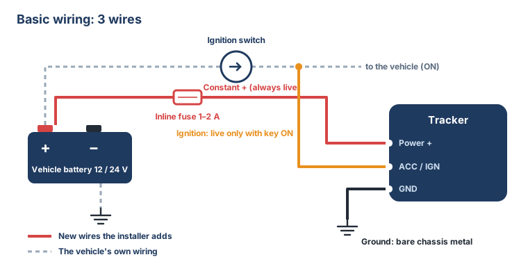
Every hardwired tracker needs three connections. The wire colours below are the usual ones; always check the label or manual of the tracker model you are fitting, because colours differ between makers.
| Wire | Usual colour | Connect to | Why |
|---|---|---|---|
| Power + | Red | A constant + line (live even with the key out), through an inline fuse | Keeps the tracker reporting when the vehicle is parked |
| Ground | Black | Bare chassis metal or the battery's − terminal | A bad ground causes resets and false readings |
| Ignition (ACC / IGN) | Orange, yellow or white | A line that is live only with the key ON | This is what tells LemursEye the engine is on: trips, idle time, fuel cost |
Finding the right lines with a multimeter
Set the multimeter to DC volts. Put the black probe on bare chassis metal.
- Constant +: a wire that shows 12 V (or 24 V) with the key out, and stays there when you turn the key.
- Ignition: a wire that shows 0 V with the key out, 12 V (or 24 V) with the key ON, and stays live while the engine is cranking and running. Some accessory (ACC) lines drop out while cranking; prefer the ignition (ON) line.
- Ground: a bolt on bare metal (scrape off paint if needed), or a ground point the vehicle maker already uses.
Take power and ignition from the ignition switch wiring or the fuse box, never from the airbag, ABS or engine computer circuits.
Why the ignition wire matters so much
Without it, the tracker cannot tell an engine running at the kerb from a parked vehicle. LemursEye then has to guess trips from movement alone: idle time and idle fuel cost show zero, and the morning digest loses its most useful numbers. An installation without the ignition wire is not finished.
Connections
- Crimp with insulated connectors, or solder and cover with heat-shrink.
- Put the fuse within a hand's length of where you take the power, so the whole new wire is protected.
- Run the new wires along the existing wiring loom and zip-tie them every 15 to 20 cm, away from moving parts (pedals, steering column) and hot surfaces.
24 V vehicles
Trucks, buses and most machines run on 24 V. The tracker must be rated for it (most are 9 to 36 V), and any relay must be a 24 V relay. A 12 V relay on a 24 V vehicle burns out.
Optional: engine cut-off (starter interrupt)
The fleet owner can block a stolen or unauthorised vehicle from starting. The safe way is to interrupt the starter circuit, not the fuel pump or the ignition: a vehicle that is already running is never stopped, only prevented from starting again.
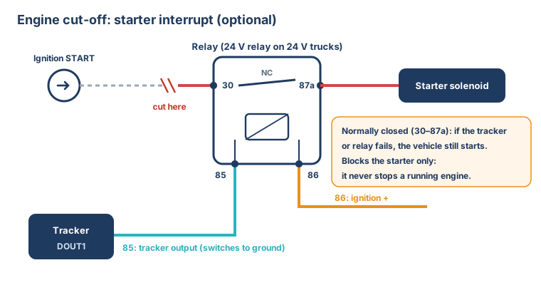
- Use the relay's normally closed contact (pins 30 and 87a) in the wire from the ignition switch's START position to the starter solenoid. If the tracker or the relay fails, the vehicle still starts.
- Relay coil: pin 86 to ignition +, pin 85 to the tracker's digital output (DOUT1), which switches to ground when the block is on.
- Never wire the cut-off so that it can stop a running engine. Cutting an engine at speed takes away power steering and brake assistance.
- The block is switched by a command to the tracker (by SMS today; see the model's setup guide).
- Test it in the handover: with the vehicle stopped and the key off, switch the output on and check the vehicle does not start; switch it off and check it starts.
Optional: sensors
- Door sensor (cold chain, cash vans): a door switch to one of the tracker's digital inputs. Note which input you used in the installation record.
- Panic button (buses, security): a push button to a digital input, within the driver's reach.
- Temperature sensor (cold chain): a 1-Wire or Bluetooth sensor, depending on the tracker model; place it in the cargo area, away from the evaporator's direct air flow.